Project Floppen
Worked on: October 2024

(This page is a work in progress)
Background
Each semester, meaning twice a year, Omega Verksted arranges a robowar event for everyone to participate in. The competition has two parts. The first challenge is to build a robot that can complete an obsitcle course, where you are graded on the time spent, how many obstacles you toutched, and the destruction of 3 soda cans. The seccond part is a fighting tournament where the robots fight each other in a small arena. Here the goal is to either incapacitate the other robot, or do the most damage in 3 minutes, or make the oponent surrender. In addition to theese challenges the robots are graded by the judges on entertainment value, and the design of the robot. This autumn, Propulse NTNU, as one of the technical organizations at NTNU, was challenged by Omega Verksted to participate in the robowar event. So me and some friends decided to get together and build a robot for the event.
Details
After doing some research, we came across this video on youtube of a flipper called Jännä, that used a snail CAM mechanism to arm a spring loaded flipping arm.
This design looked very simple, as it only required one motor to arm the flipper, and it could be armed repeatadly, yet it seemed very powerfull. We decided to use a similar design for the weapon of our robot.
For the rest of the robot, we ordered two motors and wheels from aliexpress, some motor controllers, an antenna and an ESP32 to control the robot. We had some carbon fiber plates laying around from the last time someone from propulse wanted to participate in the robowar event (they started working on it way too late), which we used for the armour of the robot. The inner structure that connected all the electronics, the weapon, the wheels and the armour was made from parts printed in PLA and PETG. So with all the parts in place, we just needed to start designing the robot so we could start production in time for the competition.
Design
As the physicist on the team, I became responsible for the design of the flipping mechanism of the robot, and had to spec the spring and the motor. We had not ordered the motor to drive the flipper in time, so the motor options were limited to what we had laying around. The goal was therefore to spec the weapon to be as powerfull as possible, while still being able to be driven by the motors we had. The strongest motor we had was a 12V DC motor with a planetary gearbox. We found a very similar motor online with a stall torque of 1.35 Nm, which became the base for the design.
Design of the weapon
I started by researching the snail CAM mechanism, and found this very usefull page on designing snail CAMs for this exact purpose by Ask Aaron. The page recommened using a parabolic spiral, or Fermat's spiral for the shape of the CAM modified to have a flat region at the small end of the spiral to provide a suitable landing area for the flipping arm. The formula for a Fermat's spiral in polar coordinates is given by:
where is a constant that determines the rate of spiral growth. To get a minimum radius of the CAM you can simply add it to this formula to get:
Aaron has an unexplained formula for calculating the "rate" based on the minimum and maximum force applied to the snail CAM, which he then uses to calculate the growth of the spiral. The formula for the rate is:
which simplifies to when . This is then used to find using:
In the article, Aaron recommends using for one unit of lift per rotation. I never really understood how this consant was derived, the growth formula looks empirical to me. I still used it for the dimensions of the snail CAM as Aaron seemed like they knew what was up.
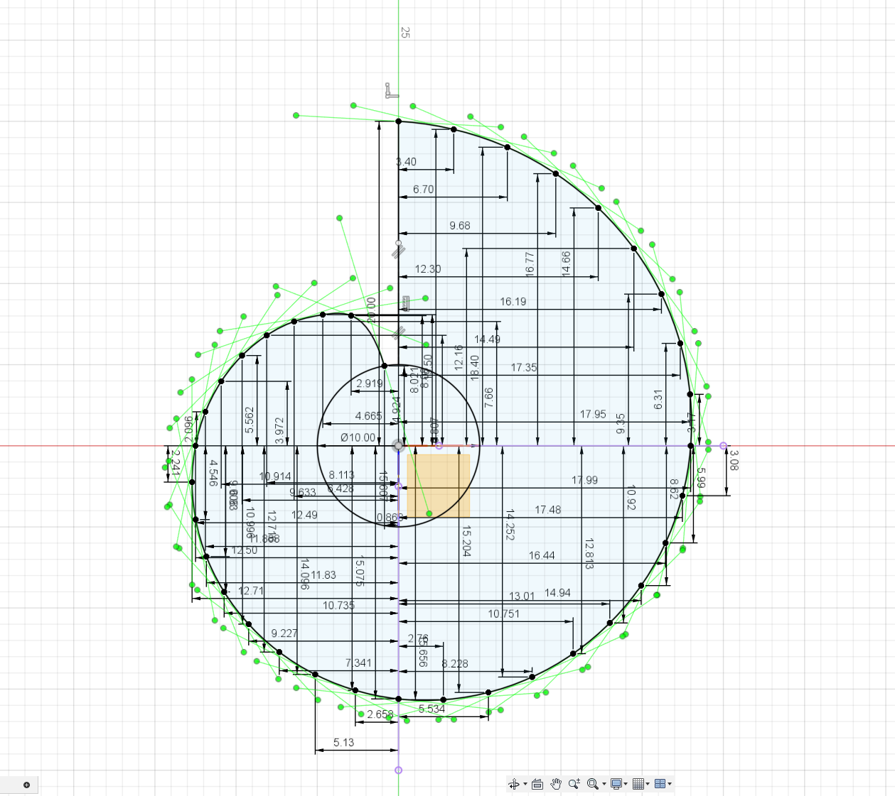
Figure 1: Sketch of the prototype snail CAM using random parameters to test the method. This was made by converting the Fermat's spiral to cartesian coordinates and manually plotting each points x and y coordinate.
From this, i could find the dimensions of the snail CAM. I only needed to find the minimum and maximum force applied to the snail CAM. This required that i speced both the spring and the designed the flipper arm so that i could calculate the force applied to the snail CAM. We had ordered some springs from aliexpress, which we didnt know the exact specs of, but which we assumed to have 100N of force when fully streched. We ended up being very unsure if theese would arrive in time, so we decided to order new ones from Sodemann, which gave much better customizability of the specs of the spring.
I started by finding the required force the arm needed to flip an opponent. The weight limit of robots in the competition was 4kg, and just to be safe, i started with dimensioning it to be able to flip a robot 3 times as heavy as that, for dramatic effect. This meant a required arm force of
By assuming that the max streched length of the spring was about 120 mm and adding 10 mm to the length for mounting, I used trigenometry to find the maximum length of the arm.
(make fig showing dimensioning trig)With a maximum length of the arm of around 255 mm, i initally designed the arm to be 200 mm long with the fulcrum at the centre of the arm. With the length of both arms being equal, the force from the spring needed to be the same as the required arm force . When it came to the force on the snail CAM, this was a bit more tricky. I vastley overcomplicated the problem at first, by calculating an effective arm length of the arm to the snail CAM and the calculating the force on this arm by calculating the torque applied by the spring. I later relized that this is not how lever arms work, and that i could simplify everything a lot by taking inspiration from how Jännä's arm interfaced with the snail. The arm of Jännä used two parts, a machined alu part for the flipper arm, and some sort of steel looking rod for the spring arm offseting the two arms from the same plane. This let the snail interface with the alu part without interfacing with the spring arm, which essentially puts it inline with the lever arm. This setup is much cleaner than the one I was planning where the flipper arm and spring arm were in the same plane, and you got another arm to interface with the snail.
(Picture compearing the two design concepts)It also took way less space, making space for the CAM to be bigger (which it turned out that it had to be). I descided to split the arm into two parts, like Jännä, to make it easier to machine for the mechanical guys later.
With this, finding the force on the snail CAM was as simple as finding the torque applied by the spring on the arm, and dividing by the distance from the fulcrum to the snail CAM. Because of the uncertainties with the torque of the motor, we decided to order one stronger and one weaker spring, so that we could test the robot with both springs and see which one worked best. The strong spring had a max charged force of and an uncharged force of , while the weak spring had a max charged force of and an uncharged force of . This gave a max force on the snail CAM of and a minimum force of .
The next step was then to calculate the required lift of the snail CAM. I started by setting that the arm should move up 30 degrees from the armed position to be horizontal when discharging it. With this it was simply just more trigenometry to get the required lift, as you just need to find the cathetus opposite to the 30 degree angle for the snail part of the arm. This looked like this:
(Picture of the trigenometry)The required lift was thus found to be 24 mm.
With the lift and the max and minimum force on the snail CAM, I could find the required dimensions of the snail CAM using the formulas above to find . I gave it a minimum radius of 5 mm, and calculated 36 points of the spiral, one for every 10 degrees, which I then manually plotted into Fusion 360 to create the shape of the CAM.
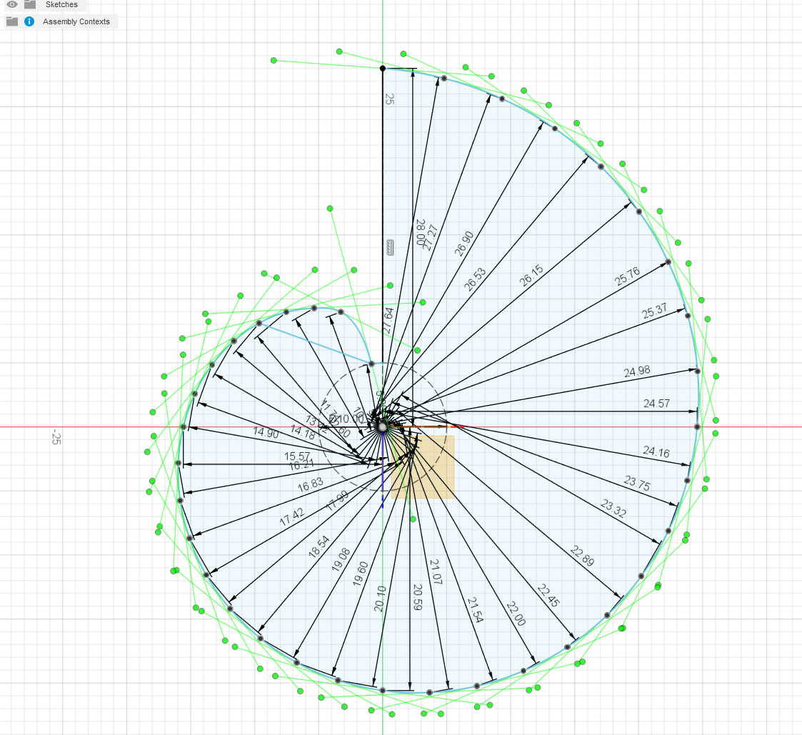
Figure 5: Final Fermat's spiral shape for the snail CAM using the calculated values, this time manually plotted in polar coordinates which cut the number of operations in half.
Since i became sick, one of my friends on the team did the final CAD of the arm based on my sketches. Since we were pushing the weight limit of the robot, he tried to add some weight saving holes in the arm, but we ended up not having time to machine them. The final design of the weapon looked like this:
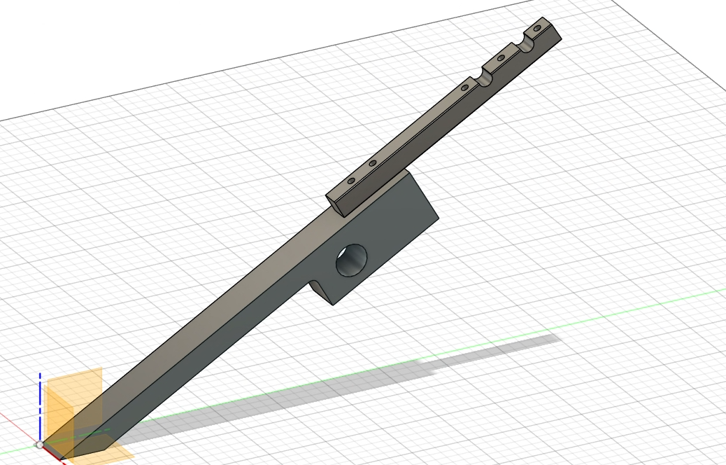
Figure 6: Final design of the weapon arm. The arm was split into two parts for easier machining, and the snail CAM was designed to be able to be mounted on the arm.
The arm was secured between two carbon fiber plates, with a rod passing through ball bearings at the arm's fulcrum. Initially, the snail cam was press-fitted onto the motor's shaft, but due to concerns about the plastic deforming, we modified the cam to include a set screw with a heated insert for a more secure clamping onto the shaft. The design allowed for the possibility of fitting both the strong and weak springs simultaneously, if needed. The remaining brackets, designed for 3D printing, were bolted to the carbon fiber plates to hold everything in place. The completed weapon assembly looked like this:
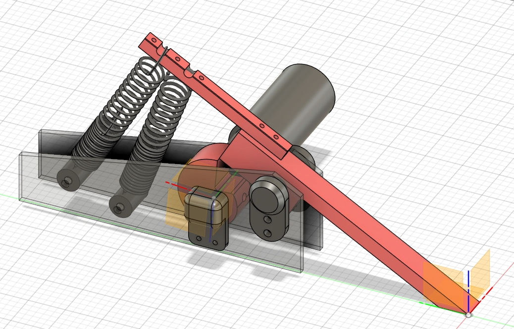
Figure 7: Final weapon arm assembly.
Design and production of the rest of the bot
With the core of the bot finalized, the rest of the bot needed to be designed so that we could start 3D printing and assembling everything in time for the compentition. We had a CADathon where we sat down and designed the rest of the bot in Fusion 360 in one evening. Here I did most of the design of the brackets that held the weapon together, while the rest was designed by the other members of the team. The design of the robot looked like this:
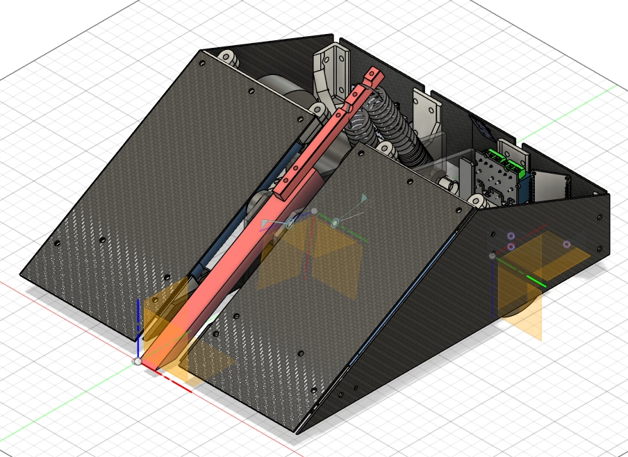
Figure 8: Final design of the robot.
The electronics of the robot had been assembed and tested before the final design of the robot was made, so we already had working electronics and software for the robot. The robot used a 2 wheel drive with a ball in the front to allow it to drive around. It was mostly armoured with carbon fiber plates, which were held together with 3D printed brackets. It was however open in the back because we ran out of carbon fiber plates, weight budget and time to cover everything.
The arm was machined from a 10 mm thick aluminum plate by one of the mechanical guys in the team, at the flex area for mechanical engineering at NTNU. The rest of the parts were 3D printed in PLA or PETG however, including the snail CAM. There were several concerns that the snail CAM would fail, either at the shaft when charging the weapon, or from the impact on the CAM itself when discharging the weapon. The snail CAM was therefore printed with 10 wall layers and 35% infill to make it as strong as possible, and mulitple spares were printed in case it failed. The carbon fiber plates were cut using an angle grinder and a dremel, and the holes were drilled using a drill press. We printed out the shapes of the plates with the holes as 1:1 machine drawings, and used them as templates when cutting the plates. Most of the assembly was done on the day of the competition, and we didnt get to properly test the robot before the competition, other than making sure we could drive it around.
Figure 9: The robot fully assembled, ready to fight!
The competition
Obstable course thing goes here
In our first round of the tournament, we were up against the robot that won the competition last semester. It was a vertival spinner, made from 3d printed aluminum. We knew that this wasnt a very good matchup for us, as the spinner could easily catch on several parts of the frame and weapon. Their bot could also drive upside down, we would need a really good flip to do much damage to them.
Here is a video of the fight, that shows how it went:
So yeah, we got oblitirated pretty quickly. It was still pretty fun to watch though, I think we had the most spectecular fight of the day. The spinner was very powerfull and well designed, and ended up taking 2nd place in the competition, only loosing to an equally impressive spinner made by someone from the TV program Newton. Our bot was pretty much out of comission after this fight, as the snail CAM broke, one of the batteries were punctured, and obviously the brackets holding the armour together shattered. So the rest of the day was spent spectating the rest of the tournament.
What went wrong?
The rapid disassembly of the robot uppon contact with the opponent is not exactly ideal for a competition like this. Since this project was a lot of fun to do, I want to discuss what went wrong, and what improvements I would have made to this design, if i wanted to participate again (😉). The spectacular disassembly of the robot despite the carbon fiber armour was simply because the brackets holding everything together were 3D printed in PLA. PLA is very brittle, and the brackets were printed to be as light as possible, which made them very weak. So when the structure came in contact with the spinner, the brackets holding the armour together shattered, dooming the robot. I got to talk to a few other teams, and the team who beat us made their structure out of TPU, which is a much more flexible material, and their robot held up much better in the fights. So the brackets will be made out of TPU next time, and maybe be designed a little differently to hold the plates better together.
Another issue we encountered was that the snail CAM exploded when we discharged the weapon. We had not tested this before the competition, but after the first battle, the snail CAM was nowhere to be found anymore. I would have looked for options for machining the snail CAM out of aluminum to make it more durable. The shape is pretty complex however, so it would have been a challenge to machine it ourselves. The options would therefore be to either order it from china, or look into engineering materials that could be 3D printed that could withstand the forces. I would order it from china next time, as the 3D printed snail CAM seems like somewhat of a gamble.
After watching it battle a spinner, i realized the design was very vurnable to spinners. If the arm isnt flush with the armor, it becomes a very good target for the spinner, and the spinner can easily catch on the flipper arm. Our design was also not very flush with the ground, which let the spinner catch on the underside of the armour, which ultimately caused the brackets to fail. I would hve tried to make it more flush with the ground to give horizontal spinners less to catch on, and start with the weapon armed. I would also be very carefull with discharging the flipper when close to a spinner, as you want to be able to re-arm the arm before the sipinner can attack again.
Overall the entire team had a blast with this project, and some of us have already started thinking about what robots we want to build for next semesters competition.